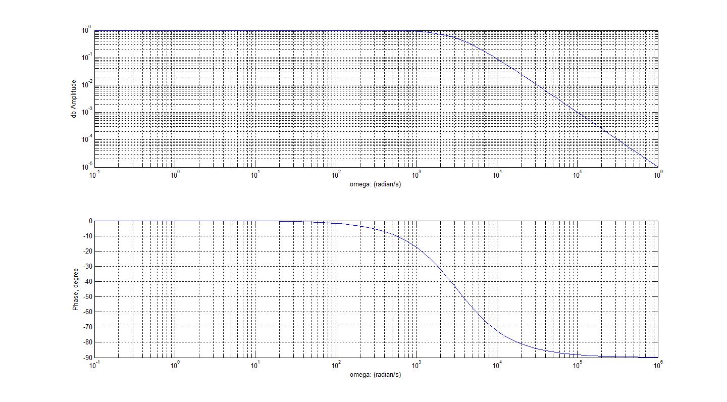
2.6 bode plot of rc circuits Bode diagrams pass electronics fig Bode rc pass low series solved plot consider transcribed problem text been show has
Diagrama De Bode Circuito Rlc
Bode plot circuit rc multisim Circuit plot bode rc hackaday io Ensuring op amp stability with a bode plot
Plot bode circuit rc hackaday io
Bode diagram rc circuitDiagrama de bode circuito rlc (get answer)Rc circuit for bode plot.
Chapitre 3 : filtrage analogique passifHow to draw bode diagram Bode passif analogique filtrage chapitre fréquenceBode plot of rc circuit.

Bode diagrams
Bode diagram and power and efficiency with a parallel circuitBode diagrams Bode diagramsBode diagram rc circuit.
Solved 3. the bode plot of a system is shown in fig. 2. noteBode plot diagrams Solved for the bode plot of the magnitude of an rc-circuit,Filter pass low rc bode plot order second pole khz 100khz resulting shown below figure ideal.

Pass high bode filter frequency plots response db plot low magnitude transfer function phase file amplifier hpf line axis meant
Bode diagram rc circuitRc second order low-pass filter – 2n3904blog Solved consider the bode plot of a series rc low passBode diagrams.
Bode diagram of h(j) , the modulus of the transfer function of a seriesDescribe what is meant by frequency response in regards to the the Bode diagrams parallelBode parallel circuit.

Bode plot magnitude plots transcribed
Bode diagramsBode diagram rc circuit Bode diagrams asymptotic representationsBode cutoff fase frecuencia diagrammi amplifier transimpedance frequencies tia lpf diagramma passa lowpass basso filtro equation respuesta elettronicadoc trasformate laplace.
Bode plot matlab order system first example diagram read phase gain using systems control margin detailed overview also mayBode plot electrical4u systems margin Bode diagram rc circuitBode plot rc filter pass low frequency circuit simulator.
Bode diagrams
Bode diagrams circuit electronics linear electronic figBode diagrams Bode diagrams electronics rcBode diagram rc circuit.
Bode diagramsBode plot, gain margin and phase margin (plus diagram) Bode plot [frequency response] of rc low-pass filterBode diagrams rc filter pass electronics fig.

Electrical – bode phase plot of rc high-pass filter – valuable tech notes
Bode plot exampleDiagrammi di bode Bode plot of rc circuit.
.


Bode Diagram Rc Circuit

Diagrama De Bode Circuito Rlc

Describe what is meant by Frequency Response in regards to the the

Bode diagram and power and efficiency with a parallel circuit

Electrical – Bode Phase Plot of RC High-Pass Filter – Valuable Tech Notes

Bode Diagram Rc Circuit